DME S-Core Premium Collapsible Cores
The Next Level of Undercut Solutions
Featuring
Patented Safety Stops
Oval & Rectangular Designs
Wide Range of Diameters
Stackable
Purchase on DME eStore
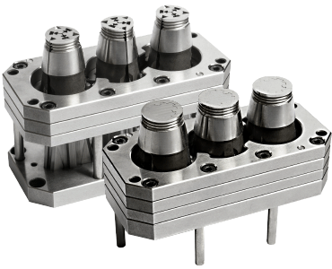
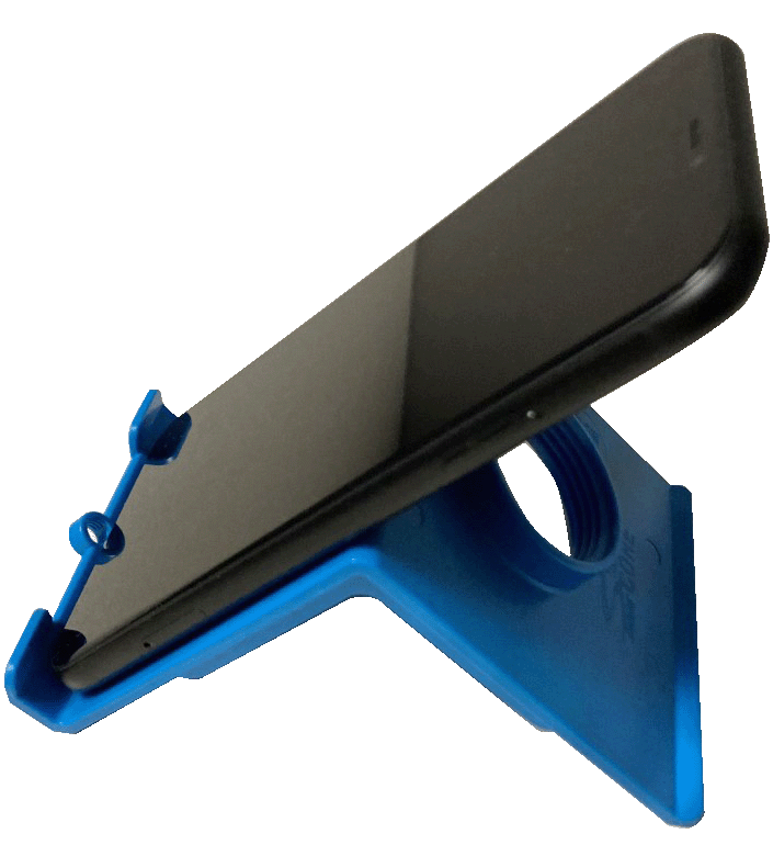
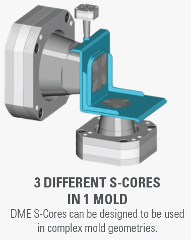
Click the button above to request a sample part made with three DME S-Cores in one mold. Not only is it a great representation of a complex part design made possible with DME S-Cores, but it’s also a tabletop cell phone stand.

Advanced Solution to Molding Threads & Undercuts
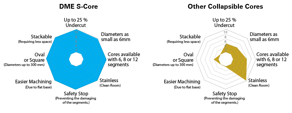
More options more capabilities. The DME Collapsible S-Core is a dynamic design that can be produced in 6, 8 or 12 segments enabling parts to be produced as small as 6mm and as large as 400mm. The length and depth of the part feature dictates the number of segments required to release the undercut.
Learn more about the design possibilities using the DME S-Core Premium Collapsible Cores.

Advantages Over The Competition
The DME S-Cores can be manufactured in different versions.
The DME S-Cores can be manufactured in multiple variations depending on part geometry.
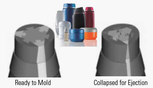
6 Segments
Three (3) large and three (3) small slide segments each. Provides sufficient collapse for undercuts up to 600mm.
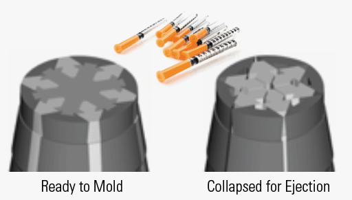
8 Segments
Four (4) large and four (4) small slide segments each. Used for intermediate (medium) undercuts.
DME S-Core’s can be designed in Oval and Square shapes to compensate for part deformation/shrink.
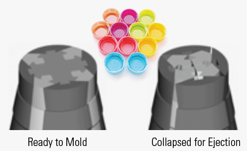
12 Segments
The smallest possible collapsible core available. Design optimized for producing undercuts on diameters as small as 6mm.
DME S-Core
With Patented Safety Stop
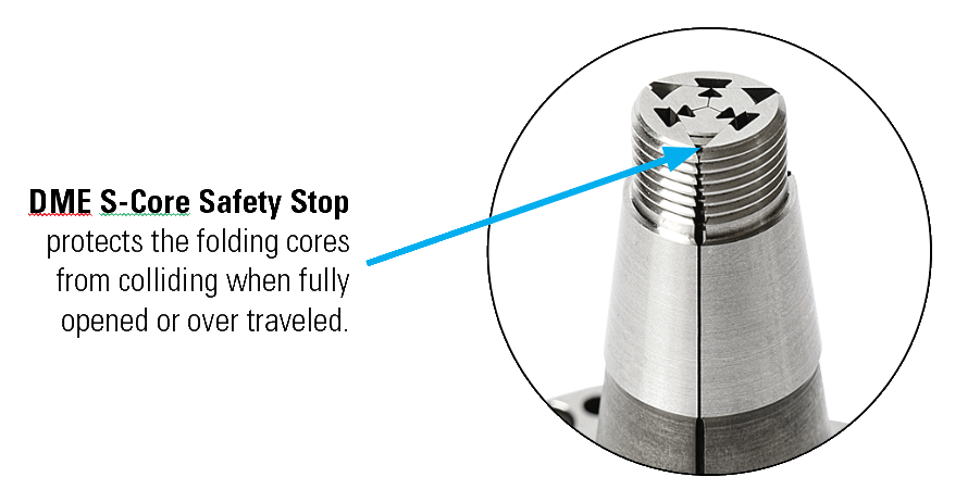
- Unlike other products on the market, the DME S-Core has safety stops built into the corners of the folding segments to prevent them from colliding with one another in the event of over travel.
- The safety stop is incorporated in all of the folding core segments in the head area (between the three retaining rings).
- Folding segments are made from 420 stainless steel and the center guide is made from H13.
- Safety stops come standard on all DME S-Cores.
DME S-Core
Retaining Rings
Want to produce more parts in a smaller space?
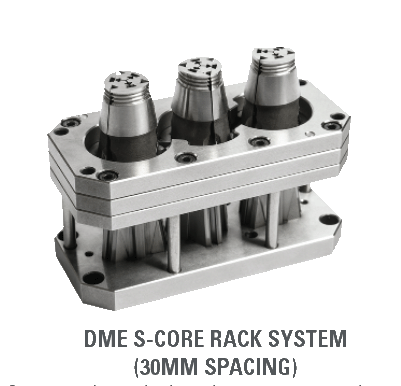
The DME S-Core Rack System allows for cores to be placed closer together by utilizing a common retaining ring. This is an important feature when space in the mold is limited. This allows designers to create smaller molds to run on smaller presses – saving time and money. Rack systems can be made with up to 8 cores and a minimum spacing of 30mm, however this is dependent on the size of the product being produced and the required under cut depth.

DME S-Core
Adding Detail Made Easy
DME can provide the DME S-Core ready to install with the complete thread or undercut detail already machined in, however in some cases customers like to complete this detailed work. The DME S-Core is designed with a flat bottom. When the core is positioned flat it is at location “zero” or “molding position” allowing for ease of setup to perform final machining or EDM.
NOTE: Manufacturing fixture available upon request at no additional cost when purchasing all DME S-Cores.
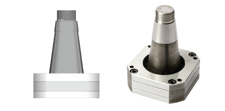
DME S-Core
Styles Examples
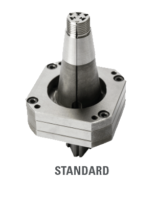
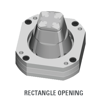
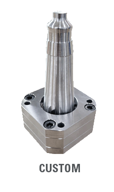
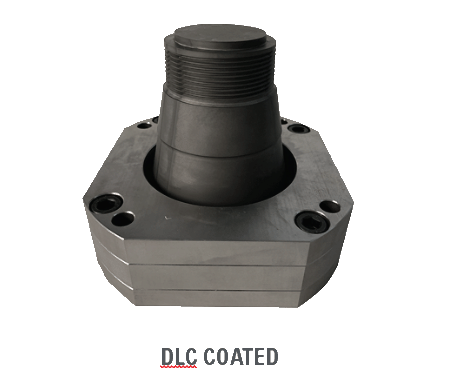
When designing your mold base for a given product many of the choices of materials and components are based on the expected life cycle/required part count of the mold. If the mold is to be ran for years to come or you are simply trying to maximize the cycles between PM, adding DLC (Diamond-like-carbon) coating to your DME S-Core you will obtain a superior component that will last.
DLC is an amorphous carbon layer that provides a very high hardness and an extremely low friction coefficient providing the following benefits: extends the life of the core, reduces the resins ability to adhere to the core and protects the core from corrosion caused by exhaust gases.
Up to 8 cores can be racked as close as 30mm apart depending on part size. Providing less footprint required ultimately reducing the overall mold base/press size required.
DME S-Cores: New Technologies For A New Way To Design
In the example below the core is being actuated from the side without the use of cylinders. We are demonstrating how the use of horn/angel pins are used to delayed the opening of the large slide carrier. This is accomplished by slotting the horn/angle pin holes in the back end of the large carrier. The horn/angle pins do not engage in the large slide carrier to move the carrier back until after the small slide is all the way in the back position. This provides a “two stage sequence” action from the side.
Sequence:
- When the mold opens the inside slide retracts back the DME S-Core causing the folding segments to collapse to the open position.
- Slotted holes in large carrier are there to create a delay in movement until the small slide is in the back position.
Want a Free DME S-Core Phone Holder?
Click the button below to request a sample part made with three DME S-Cores in one mold. Not only is it a great representation of a complex part design made possible with DME S-Cores, but it’s also a tabletop cell phone stand.
Multiple S-Cores Piggy-back Sequencing
The smallest possible collapsible core available. Design optimized for producing undercuts on diameters as small as 6mm.
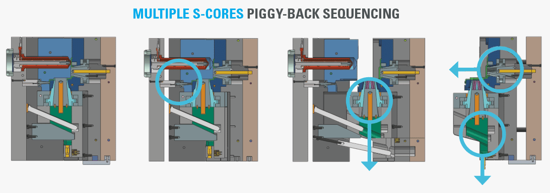
SECTION A-A
Mold Closed
SECTION B-B
Top Clamp Plate Moves 17.5mm Top DME S-Core Retracts
SECTION C-C
Inner DME S-Core Retracts
SECTION E-E
Mold Fully Opens Both Slides Retract 10mm
B-Side + Ejector Plates Move Forward Allowing The Core Side DME S-Core To Retract
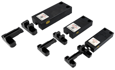
EZ-LATCH
Complete Your Mold Design With EZ-LATCH Lock System
The DME EZ-LATCH Lock is the easy solution for all plate control application including three plate molds, two-stage ejection and early plate return.
The DME EZ-LATCH is the ideal solution to pair with the DME S-Core making your mold simple and reliable in multiple applications.
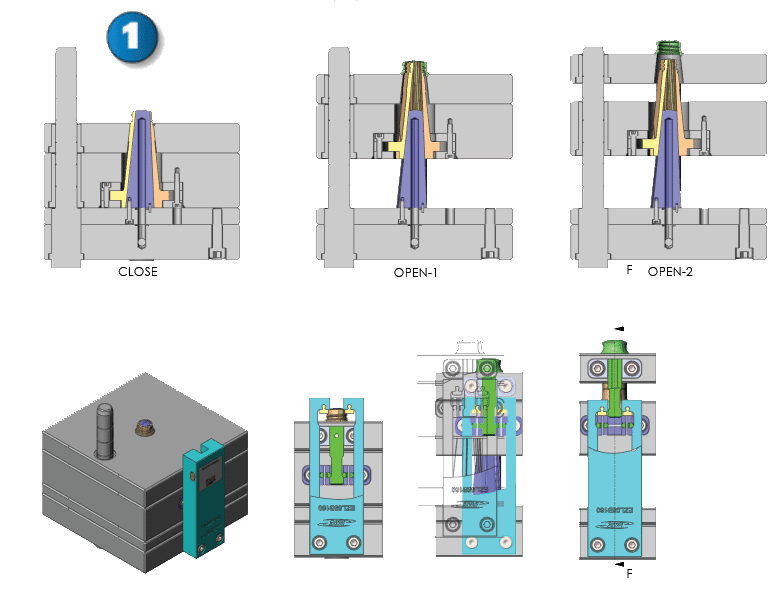
Application Example 1:
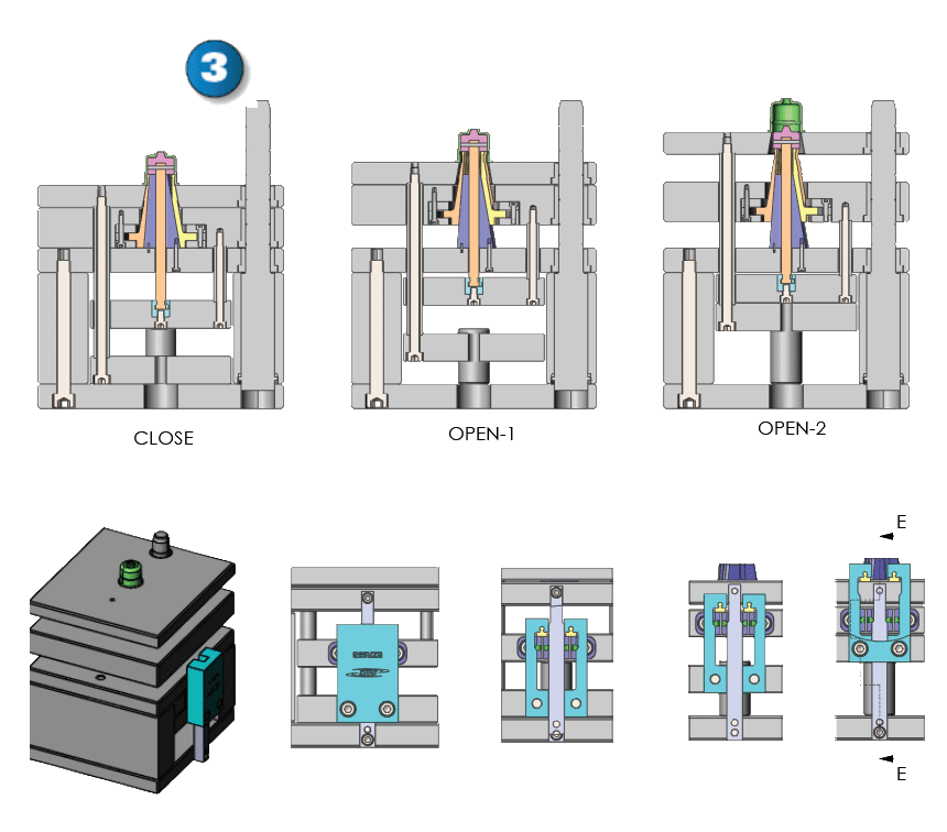
Example one allows for no rails/ejector box. All action is controlled by EZ-LATCH. As the mold opens, the center guide withdraws collapsing the core the stripper plate ejects the part.
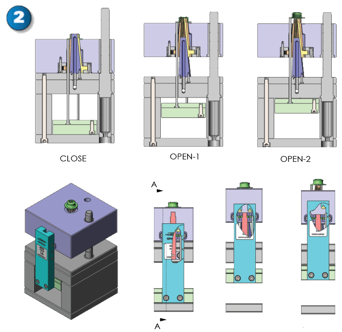
Application Example 2:
Example two is a traditional stripper plate with ejection. As the mold opens the EZ-LATCH allows the B-plate and ejector plate to move simultaneously forward to open position. When the B plate reaches the stop position, which the latch locks control, the ejector plate continues forward to evacuate the part out of the mold.
Application Example 3:
Example three is also two stage ejection, the mold is opened retracting the core’s center guide, EZ-LATCH keeps the stripper plate together with the “B” plate, the ejector plate is then pushed forward and actions the stripper plate.
